Early British gas turbine development

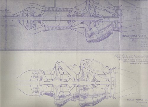
To move on to the later developments at Derby we need to retrace our steps and understand the trials and tribulations of Power Jets and Rover. The technical side of the story- in detail for the WU and W1 and less so for W2 can be found in the First James Clayton lecture which can be downloaded here. Note you will have to pay if you go via Sage!
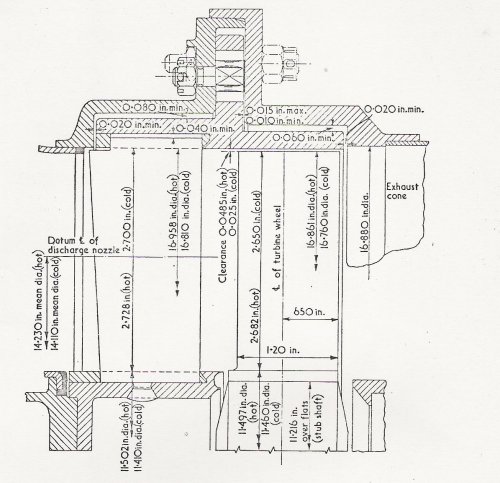
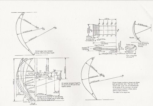
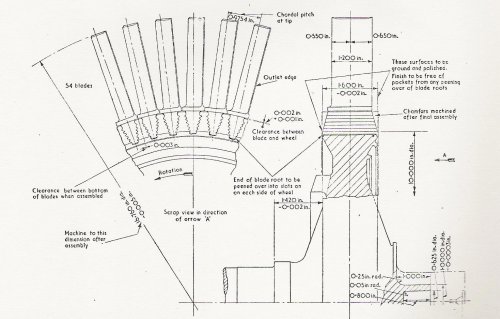
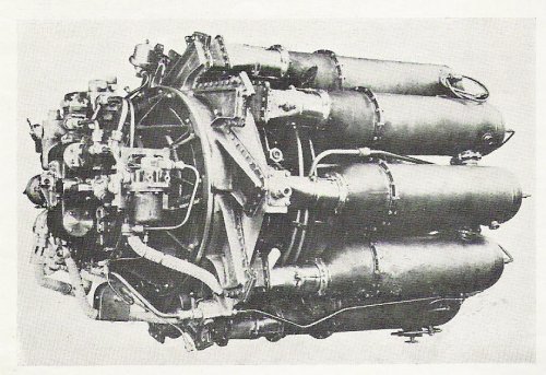
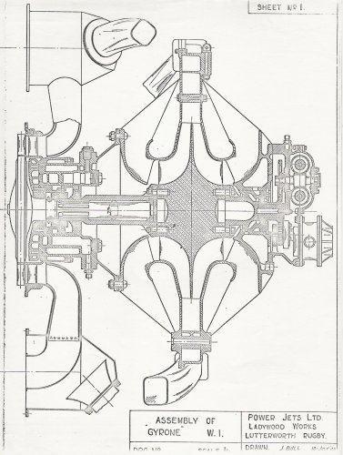
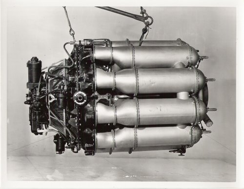
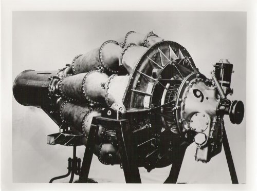
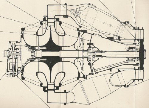
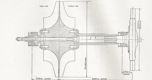
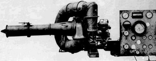
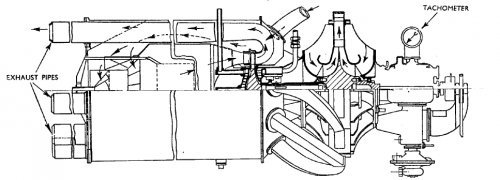
We will pick up the story as the W1 needs to be uprated. Jim Boal gave me a copy of his W1 drawing (below) and he will feature in the Tay story later.. he was unique in that he had continuity of working first at PJ, then Rover and transferring to RR. The W1 was basically a flightworthy redesign of the WU based on the same dimensions for rotating machinery.
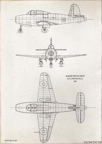
The idea for an aircraft (extract from On the aerodynamics of the Gloster E28/39 – a historical perspective by B. J. Brinkworth, the Aeronautical Journal June 2008:
"Gloster Aircraft Company had become part of the Hawker Siddeley Group in 1934. In 1939, the Company was producing the first of its Hawker Hurricanes, of which 2,750 were eventually built at the Gloucester plants. The Hurricane had been in service for barely two years, and so it will be appropriate to weigh features that emerged in the E28 against those already proven in the Hurricane, and, as the design proceeded, with Hawker’s successor, the Typhoon. This aircraft was also produced in quantity at Gloucester in due course.
The definitive version of the Whittle engine, around which the Specification was to be written, was the W2, intended to produce a
sea-level static thrust of 1,200lb. At a high cruising speed, this engine would give a thrust power comparable with that of the Rolls-Royce Merlin II installation of the Hurricane II, which was then going through the factory. However, the weight of the power-plant would be around a third of that of the Merlin and its associated equipment. Thus, a lighter and smaller aircraft could be envisaged, having correspondingly lower drag, with power available that would enable substantially higher performance to be obtained. The improvement would be greatest at higher altitudes, where the thrust of the jet engine was predicted to fall off less with height than that provided by a piston engine...............
........
Even in plan view, the fuselage still seems tubby, perhaps due to its size relative to the wings. The maximum width of the fuselage is around one-sixth of the span, twice the proportion for the Hurricane, for example.
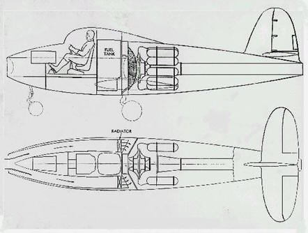
There was discussion on the effects of the flow required by the engine on the internal duct flow and external airflow. The nose intake and the ducting up to the engine bay were initially designed around the air mass flow-rate of 26lb/sec at sea level, then predicted for the W2 engine at maximum rpm. Whittle had assumed in performance calculations that the energy loss in the ducts would be 10% of the energy at inlet, a substantial penalty. Carter had accepted his advice that the mean velocity in the outlet of the duct, at the engine plenum chamber end, should not exceed 100ft/sec (though RAE representatives thought that the loss would not be 10% even if a mean velocity of 200ft/sec were used, as had been initially proposed by Gloster). At the nose, the diameter of the intake in the Intermediate design had been 18in, with an area of 1⋅76ft².
In the Final version, the diameter is 21in (area 2⋅4ft²), corresponding to a nominal mean inlet velocity of around 150ft/sec at the design point. This would have allowed also for the additional flow expected to be required to provide cooling air for the rear turbine bearing of the W1A and W2 engines, which would be used after the first few flights
Two ducts convey the air from the nose intake to the engine plenum chamber. Bifurcating the flow immediately after the intake, these are straight in elevation, passing along the sides of the fuselage, around the nose-wheel bay and the cockpit, to form two smooth curved tubes. Each has a non-circular and varying cross-section, with three full-length streamwise dividers. It would not have been a simple matter to calculate the flow losses in these, but no records of test measurements have been found. Significant further
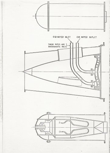
losses would have been caused by the radiators, that were initially fitted at the engine bay ends of the ducts. These had been provided for cooling the W1 engine intended to be used for the taxying and initial flight trials, which, being based on the test-bed models, had a water-cooled turbine bearing. Fortunately, air-cooling became available for the W1A version, fitted after early trials with W4041, and for the W2 engines for the main series of tests with both aircraft, so the radiators were not then required.
The delivery of the intake air into a plenum chamber ahead of, and surrounding, the engine compressor casing meant that two bulkheads and part of the airframe structure were subjected to an internal pressure difference. It was agreed that this should be based on the full stagnation pressure at sea level maximum speed (410mph), about 3lb/in². Later, a design value of 5lb/in² was adopted, with a reserve factor of 2. This perhaps represents the first time that a substantial part of the primary structure of an aircraft had to support a pressure difference of this magnitude."

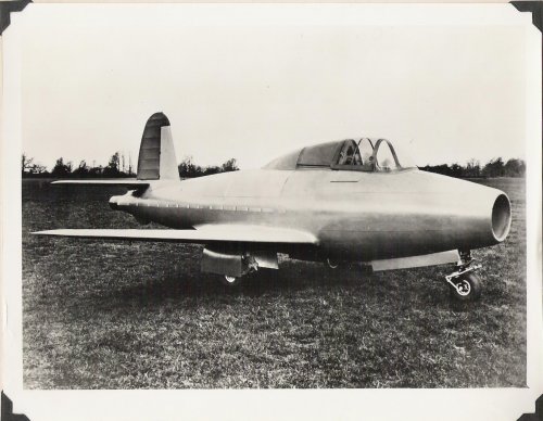
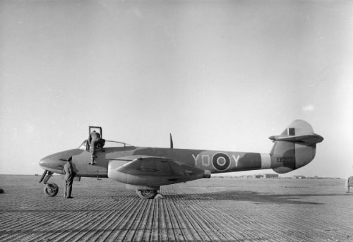
I have added drawings and photo of the aircraft to supplement the text.
 

Attachments

  • PJ-W1-section rotating mcy.jpg
    PJ-W1-section rotating mcy.jpg
    504.1 KB · Views: 335
  • PJ-W1-section cc and tailpipe.jpg
    PJ-W1-section cc and tailpipe.jpg
    294.4 KB · Views: 294
  • Gloster E28-39.jpg
    Gloster E28-39.jpg
    311.1 KB · Views: 77
  • Gloster E28-39-GA.jpg
    Gloster E28-39-GA.jpg
    370 KB · Views: 91
  • Gloster E28-39-engine layout.jpg
    Gloster E28-39-engine layout.jpg
    25 KB · Views: 94
I suppose this as good an opportunity as any to thank you for your efforts, tartle! I've been reading your notes with great interest and the fascinating insights they provide into this pioneering era are much appreciated, do please keep it coming!
 
Thanks... it is difficult to gauge whether it is useful without feedback.. which also helps steer the material.. more technical/less technical? more people ... etc.
Incidently the gap in transmission was due to a very early rotating engine the Gnome Omega 50 hp rotary no. 377 which belonged to Maurice Egerton, pioneer aviator 1909-14... he lived at Tatton Park and the engine is in the Mansion.. they have an exhibition of his exploits until beginning of May which I helped put together... he inspired Stanley Hooker who mentor Geoff Wilde who mentored me... but that is another story!
 
Mike Evans who is emeritus president of RR Heritage Trust is a patient man. When he was in RR Public Relations dept at Derby he would patiently reply to a certain schoolboy's stream of questions that arrived quite regularly... later when I joined RR as an apprentice engineer I was assigned to work a period with him. Mike got his own back and helped my knowledge acquisition by handing all the schoolboy and other questioners's letters to me with a quip "off you go then, find the answer to that one!"
Mike wrote an article about Lord Kings Norton (Roxbee Cox) in the April 1999 commemorative edition of the Aeronautical Journal:
"For his [Whittle's] WU engine in its various forms - the W1X and the W! engine that flew in the Gloster E28/39 at RAF Cranwell on 15th May 1941 - Frank Whittle was continually short of money and, therefore, inevitably, of hardware. Initially this had been sourced from BTH with specialist help on components like combustors from Laidlaw Drew and Shell. To these sources in 1941 was added Rover which, with support from Lucas, was to build complete engines for Power Jets. Additionally, and informally, Rolls-Royce made parts to help Whittle directly and to support Rover on a sub-contractor. But it got more complicated than that. Whittle's W! was followed by the more powerful yet more compact W2. When testing showed the need for improvements, Whittle designed the W2B and it was this engine which Rover was given to build. Progress did not stop at Lutterworth, however, the W2B was followed by the W2/500 and ultimately the more powerful W2/700."
The MAP by this time is supporting Halford's H1, RR's WR1 designed in Derby (with PJ support) whilst at Barnoldswick Rover are going off on their own initiative without consulting Whittle.
Mike continues, "Capt. Spen Wilks [Managing Director] of Rover proposed a joining of forces with Hives in February 1942, long before relationships with Whittle came to a head. When Rover 'straightened out' the W2B/23 to create the B26 -forerunner of what was to become the RR RB37 Derwent I - Whittle was furious. Understandably he saw it as a further diversion and, therefore, delay in getting the jet engine into service against the enemy." ....tbc
 
Roxbee Cox arrives...
Mike Evans continues:
"Such was the multiplicity of experimentation when Roxbee Cox first took office at MAP in 1940, and it continued to complicate itself in 1941. A first glimmer of a way forward rests in a letter from Roxbee Cox to Hives dated 21 August 1941: 'I do not expect there will be any obstacle in the constitution of a committee for pooling our gas turbine facilities and experience but it will take me a few days to make sure of everyone's co-operation.' On 3 October 1941, a letter went out over the signature of Air Marshal Linnell of MAP. It began:
'Dear Sirs,
As you are aware gas turbine development is now going forward in various organisations and along several different lines, and it is clearly desirable to ensure economy in our efforts to produce power units of this new kind as quickly and efficiently as possible. that all parties should collaborate.
To encourage and guide collaboration, it has been decided to form a committee under the chairmanship of Dr Roxbee Cox on which all firms engaged on gas turbine projects will be represented....."
Thus was born the Gas Turbine Collaboration Committee (GTCC) and the beginnings of drawing all the efforts to a focus. It was not an easy or painless process and the losers were the creators of the gas turbine themselves. In the case of the RAE this was inevitable..... its role was recognised as a research and test agency. In the case of Power Jets Ltd - and Frank Whittle in particular - the case was very different.....tbc
 
Jim Boal, who we will remember is the continuity man, said that "there was no W2 design". It was a new an unproven design that Rover were trying to get into production. The extensive use of complex sheet metalwork meant that the production job could not be automated or deskilled by the use of machines so the amount of skilled labour determined the slow build up to quantity production. G. P. Bu;man who reported to Linnell and was director of both research and production wrote pithily in his memoir:
We [Bulman and Tedder] had all long since realised that Whittle was his own worst enemy. He was quick to invest any discussion with the venom of suspicion, scavenging throughletters and minutes of meetings looking for odd words and phrases he could pick on to suggest they were deliberately ambiguous and revealing a sinister influence behind the scenes. He saw us as determined to do him down lest his jet became damaging to the piston aero engine, the powerful array of engine firms and my department. I told him one day in a moment of exasperation that he was the most impossible man I'd ever had to deal with! He never forgot it.
Whittle had met with Tedder (Director General for Research) and for the first time Wilfrid Freeman (head of MAP) on May 9 1940. Whittle protested that orders to Rovers should be by sub-contract through Power Jets; failing that he argued that he should be formally made chief engineer of the whole project. The two officersdid not agree. Tedder later remarked that Whittle was a 'prima donna - very important but needed careful handling.
Rather than summarise Bulman's view of the W2 development and production 'complication' I have copied the relevant pages from the RRHT Publication Historical Series No 31 below.
 

Attachments

  • g p bulman memoir p322-23.jpg
    g p bulman memoir p322-23.jpg
    659.3 KB · Views: 77
  • g p bulman memoir p320-21.jpg
    g p bulman memoir p320-21.jpg
    822.8 KB · Views: 65
  • g p bulman memoir p318-9.jpg
    g p bulman memoir p318-9.jpg
    832.4 KB · Views: 71
You may gather from the above that Frank Whittle was desperately trying to keep control of the detail design and development of his 'baby' and reacted furiously to Adrian Lombard's enthusiastic redesign of the B23. Whittle had originally adopted the reverse flow layout to achieve a short engine to minimize shaft whirling problems. Whittle himself had ideas for a future development of the engine with straight through combustor air flow but felt that the priority was to get Gloster some engines for the Gloster Meteor. He was upset both by Rover's team going behind his back but also the fact that he had lost design control at Barnoldswick.
Returning to Mike Evans... he wrote that:
"As matters progressed, it became logical in the eye that Rolls-Royce should take over Barnoldswick and Clitheroe. The famous 5/- (25p) meal at the Swan and Royal did take place late in December 1942 as Stanley Hooker described but that was a handshake on what was, in reality, a MAP directive inspired, one suspects, by Roxbee Cox. He, in fact, wrote to Hives on 15 December 1942 following a meeting three days earlier at which they, Wing Commander Whittle and A. G. Elliott, Rolls' chief engineer,had been present. Roxbee Cox had undertaken to lay a series of points which had been agreed before his superiors. These included:
(a) Production of Power Jets W2/500 engine to be in the hands of Rolls-Royce.
(b) The facilities to be used to be those at Barnoldswick.
(c) Research on, and development of, centrifugal type units to be in the hands of Power Jets Limited at Whetstone and Lutterworth.
In the event it did not happen that way. Rolls-Royce did take over frrom Rover. Hooker moved to Barnoldswick at the very beginning of 1943 and the official handover day 1 April. Rover, in exchange, took on board the Meteor tank engine over an extended time horizon. But the factory was not cleared of all work to make way for the W2/500. Rolls-Royce continued with the W2B/23, launching it into service as the Welland in the Gloster Meteor fighter with 616 Squadron in little more than a year.
 

Attachments

  • W2BdiagramT.jpg
    W2BdiagramT.jpg
    34 KB · Views: 85
  • RR-G2079-RB23 Welland-rear.jpg
    RR-G2079-RB23 Welland-rear.jpg
    304.8 KB · Views: 79
  • RR-G2081-RB23 Welland-front.jpg
    RR-G2081-RB23 Welland-front.jpg
    417.1 KB · Views: 73
  • RR-whp3665-B23 Welland-3 quarter front.jpg
    RR-whp3665-B23 Welland-3 quarter front.jpg
    312.5 KB · Views: 70
  • RR-WHP3663-RB23 Welland-side.jpg
    RR-WHP3663-RB23 Welland-side.jpg
    276.5 KB · Views: 77
  • gloster meteor I of 616sqdn at Manston.jpg
    gloster meteor I of 616sqdn at Manston.jpg
    46.7 KB · Views: 79
Now here is some good news and some bad... the bad is that I have mislaid my B26 notes; the good news is that while looking for them I found my RB60 notes which will be useful when we progress. In the meantime what we can say is that the spectre of shaft whirling in an engine was overcome by putting a spherical coupling designed by Lombard and a third deep ball bearing in the centre of the shaft. The coupling enabled varying axial loads to be transmitted as well as the torque loading whilst all remained in perfect balance.
The photo below shows STx 9.. the engine built by modifying the B23.. it is what we would now call a proof-of concept demonstrator. Lombard's team, pleased with the results redesigned the B26's inlets for increased air flow, and thus thrust. Eventually this became the RB37- the Derwent
 

Attachments

  • RR-whp25054- STx9-3 quarter front.jpg
    RR-whp25054- STx9-3 quarter front.jpg
    274.9 KB · Views: 98
  • Lombard coupling.jpg
    Lombard coupling.jpg
    153.5 KB · Views: 121
For those of us who aren't gas turbine engine specialists, please explain 'shaft whirling'........


cheers,
Robin.
 
For a rotating shaft there is a speed at which, for any small initial deflection, the centripetal force is equal to the elastic restoring force. At this point the deflection increases greatly and the shaft is said to "whirl". Below and above this speed this effect is very much reduced. This critical (whirling speed) is dependent on the shaft dimensions, the shaft material and the shaft loads . The critical speed is the same as the frequency of traverse vibrations.
Like a tuning fork a rotating shaft may go into transverse oscillations at its natural frequency. If it is slightly out of balance (and all real practical shafts are, if only minutely) then the resulting centrifugal force will induce the shaft to vibrate quite noticeably. Think of what happens if a balance weight falls of the rim of your car's front wheel. The vibration can be a little all the team but get worse at certain speeds... that's whirling. When the shaft rotates at a speed equal to its natural frequency then the vibration can build up and cause blades to scrape their casing and sometimes the shaft itself can fatigue and fail... also bearings can overheat.
The formula for a simple shaft between 2 bearings is the formula shown below:

where f is first critical speed; the deflected shape looks like a skipping rope.
I can define in detail if you like; but the main thing it highlights is that I, the moment of inertia is on the topline and the length between bearings is on the bottom. This means increasing diameter (I increased) increases the natural frequency and increasing length L drops it.
So if we look at the W2B/500, which has 2 bearings,we can see that L is 17.125 inches. The straight through flow Derwent V has three bearings but each span is quite large in comparison:
front to middle bearing is 23.7 and mid to rear is 21.94 inches making a total of 45.64; some 28.515 inches longer than Whittle's reverse flow engine... hence the need to rethink the bearing and Lombard coupling arrangement.

Hope this gives a feel for why Whittle and Lombard made their particular choices. The actual calculation of whirling speeds is more complex and takes into account the masses of turbine and compressor wheels etc. It is best to keep the critical speeds of the rotor above the design peak speed; if this is not possible then making sure the engine passes through the critical speed as fast as possible is an acceptable approach.
 

Attachments

  • whirling speed.jpg
    whirling speed.jpg
    5.7 KB · Views: 400
  • Derwent V rotating assembly diag.jpg
    Derwent V rotating assembly diag.jpg
    537.1 KB · Views: 84
  • PJ-w2-500 rotating assembly dwg.jpg
    PJ-w2-500 rotating assembly dwg.jpg
    185.9 KB · Views: 82
Many thanks for the explanation, so, if i understand correctly, it's basically a resonance problem, made more severe by increasing the engine shaft length:diameter ratio. Therefore, by splitting the shaft in two, by means of a Lombard coupling, you get two short, thick shafts, with high natural frequencies, which should avoid this problem.
Would I be right in thinking that this is a similar problem to that suffered by the TSR.2's engines, and also the (infamous) ABC Dragonfly, though that of course was a piston engine...


cheers,
Robin.
 
Little work was done on the B26 until Rolls-Royce took over the Barnoldswick facility and had received four engines, as well as 32 B23s.
The latter engine became the first gas turbine aero engine to go into series production in October 1943. 167 Welland B23s were manufactured at Barnoldswick, before switching to the B37 Derwent, as the developed B26 was known.
 
Robin,
The ABC Dragonfly had a torsional vibration mode that sat on the operating speed of the engine leading to fatigue failures of the crankshaft after 2 hours running! This was the first time that vibration threatened to ground an airforce if the war had continued and led to a great deal of theoretical work with a Major A D S Carter deriving a way of calculating these resonant frequencies which was still good for Merlin calculations when that was being designed. The Olympus problem was vibration... I have some details that I will dig out.
Incidentally L F R Fell told me that in 1919 he had all the Dragonflies buried as the best way of disposing of them!
 
Robin.. your thought on Olympus was correct...
John Wragg was the TSR2 development engineer at Bristol. He has said that:
“Indeed the worst problem that dogged the engine for the TSR2 in its development programme was the behaviour of the low pressure shaft. A much longer shaft was fitted to the 22R than had been in use on the earlier Olympus engines and that was, in part at least, as a result of trying to keep the engine bearing compartment as cool as possible in the much hotter environment that was going to be encountered in supersonic flying.
But unfortunately that change also resulted in the design of a shaft which was capable of being excited in vibration by a number of stimuli, one of the most significant being the resonance of a shaft mode with over-fuelling of the reheat system; this had been discovered immediately prior to the first flight of the TSR2. It was necessary to revise the fuelling of the reheat system at that stage and subsequently to introduce a completely new schedule to ensure the over-fuelling and consequent excitation was avoided.”
 
This is the University of Propulsion. Marvellous stuff.

How many pioneering aerospace engineers actually lacked the apocalyptic curmudgeonitude of Whittle, Johnson or Wallis, to name but three?
 
Before we move on to the RB37 Derwent engine it is worth putting Power Jets development efforts into perspective.
The first engine Whittle built was a 'proof of concept' test engine. Starting off with a single volute (rather like the RAE test units of the same era, although unknown to Whittle), Whittle knew this would deliver the air as a free-vortex flow to the combustor and ultimately the turbine blades and vanes. This gives a whirl velocity that varies, across the annulus, inversely as the radius. Whittle had left the detail design of the blade to the BTH engineers who, unfortunately designed blades according to steam turbine practice of the day, i.e. assuming whirl velocity was constant across the annulus. The result was that the turbine blades had only about half the twist they needed to perform well. The first build of the WU ran on 12 April 1937. A large amount of effort had to go into overcoming the turbine problem and other issues resulting in many minor modifications during the period April-August 1937.. without much improvement in performance. Whittle decided a major reconstruction was needed and so, in his words the 'second edition' was made. It had the same rotating assembly except for turbine blades, but in many other ways was a major tear up. The engine did not last long as the turbine disc exploded after about 5 hours running, in May 1938. The third configuration, i.e. the second rebuild, had a major change to the diffuser and combustor. The combustor was changed from a single chamber to ten smaller chambers and the single volute became ten each feeding a combustion chamber - the engine was beginning to resemble the reverse-flow configuration we are familiar with today. Each combustion chamber discharged the hot gas flow through a ring of nozzle guide vanes into the turbine. The vanes and blades were designed on free vortex principles. The rig with the third configuration ran in October 1938. Problems were immediately apparent in the combustion chambers but the compressor and turbine were also troublesome. With this engine considerable progress was made. On 30th Dr Pye, Director of Scientific Research, witnessed the engine run up to 16,000rpm and was highly impressed. The following month the Ministry agreed to buy and loan back the WU engine. Also an order was placed for a W1 flight engine as well as an order on Gloster for the E28/39 aeroplane and design of both commenced.
Work continued using the WU until February 1941 when a failure of the turbine disc between the blade roots resulted in damage beyond repair.
The W1 flight engine was essentially the WU but with lighter construction. Water-cooled jackets for the turbine disc were similar to the WU but the rear water jacket was eliminated.
In order to gain time a similar engine, the W1X, was constructed from WU spares and W1 components rejected as non-flightworthy. This engine enabled Whittle to carry out a great deal of development work in advance of the W1 and was in fact fitted in the E28/39 for taxiing trials. In fact one of those trials resulted in the aeroplane performing a hop making the W1X the first Whittle engine to leave the ground!
The W1X experience paid off. The time taken from when W1 went to bench test to completing ten hours of flight trials was only 46 days.
British Thompson Houston (BTH) were responsible for the manufacture of both the W1 and W1X on sub-contract to PJ. To increase efficiency the turbine had 72 blades compared with 66 on the WU.
The W2 was now being designed and in order to check out some of the special features another engine was constructed to test out some of its features. This was the W1A, which incorporated an air cooled turbine disc, using vanes mounted on either side of the disc. Tests showed that having vanes on the bearing side only was sufficient to achieve the desired level of cooling.
A design principle, among others, of these engines was to use as high an exhaust velocity as possible, partly to get the highest mass flow for a given turbine size but also to reduce the degree of deflection needed through the blading. The W1 design target was a 1,000 ft/sec; the figure for the W1A was raised to 1250 ft/sec which corresponds to an exhaust mach number of 0.7. At such high speeds the flow is critical to sizing the diameter. The turbine disc cooling air discharging at the rim of the turbine disc formed a thick boundary layer on the inner wall of the jetpipe causing choking in the jetpipe. This in turn, Whittle reasoned was causing the compressor to surge. Removing the vanes at the rear of the disc reduced the outflow of cooling air and this cured the surging of the compressor.
 

Attachments

  • Whittle-WU-first build.jpg
    Whittle-WU-first build.jpg
    15.4 KB · Views: 269
  • Whittle-WU-second build.jpg
    Whittle-WU-second build.jpg
    174.7 KB · Views: 280
  • Whittle-WU-third configuration.gif
    Whittle-WU-third configuration.gif
    75.3 KB · Views: 284
The problem of thrust.
You may have noted that every new version of the Whittle engine seems to be accompanied by yet another version... this was driven by a desire to achieve the target thrust necessary to get first the E28/39 in the air and ditto the Meteor, with integrity and reliability also being important.
The WU engine was designed for a thrust around 1,300 lb but never achieved more than 1,000lbt.
The W1 was designed for 1,240 lbt but was cleared for flight at 860 lbt. In fact it could achieve 1,000 lbt for short periods.
The W1A was designed for 1,470 lbt but achieved 1240 lbt.
The W2 was designed for 1,000lbt but was really a failure, never achieving anything like enough power.
The W2B was designed for 1,600 lbt and after a considerable development programme achieved a 100 hour development at this rating in April 1943.
The W2/500 was designed for the same thrust and the design figure was actually achieved as soon as testing began on 13 September 1942, 6 months after design commenced.
The W2/700 achieved its design thrust of 1,800 lb very quickly and soon its rating was raised to 2,000lbt; later modifications enabled 2,500lbt to be achieved. It was essentially an improved /500 with more effective blower and longer turbine blades.
 

Attachments

  • whittle_W2700_hires.gif
    whittle_W2700_hires.gif
    83.3 KB · Views: 288
In case you are wondering why I keep on about the W2/500..... when Stanley Hooker told Adrian Lombard to get on with the straight through engine to replace the Welland he took the best of the B26 (STx9) and the best features of the W2/500. Using as much of the B23 as possible Lombard's team came up with the B37 Derwent 1.
The improvements in performance of the W2 series came about through the interplay of several factors.
Compared with the W2B the W2/500 had a larger hub/tip ratio which permitted an increase in mass flow. Also fewer turbine blades of longer chord were used; the number used on the W2/500 was 54 each with a chord of 1.4 in., compared with 72 blades of 0.8 in chord. The change to fewer, larger blades was made on the recommendation of the RAE after the W2B suffered a number of turbine blade failures. The new blades were more resistant to the gas bending forces (lower stresses) and minor damage from solid particles passing through the annulus.
Metallurgy was key to development of a light, reliable engine. The advent of Whittle's gas turbine created the need for stronger, more durable alloys capable of high-temperature service When the WU was designed the best available material was Firth-Vickers 'Stayblade' and this was used for both disc and turbine blades. By the time the W1 was on the boards, F-V had produced an improved alloy- Rex 78 and this was used for the blades. But the first to answer the challeng was Leonard Bessemer Pfeil, who is credited with the development of Nimonic alloy 80 in 1941, at Henry Wiggin's research facility in Hereford. This alloy used for the blading was introduced into the later stages of the W2B development programme and in the W2?500 and /700 from the start.
The top two development issues that kept the W2B engineers awake at night were surging of the compressor and turbine blade failures. Some blade failures were a secondary consequence of a failure elsewhere. A piece of combustion chamber that had broken off could pass through the rear of the engine, notching blades on the way and this often led to blade failure. One series of failures was odd. Sometimes blades failed at the root sometimes half way up and occasionally close to the tip. Resonance would be expected to produce failures at the same place. Eventually it was realised failure was caused by a thermocouple mounted in the exhaust duct 3 inches downstream from the turbine. It was adjustable radially across the annulus and Whittle believed that there must be an upstream pressure field ahead of it of sufficient magnitude to interfere with the flow through the blades as they passed through it. It seems this was a correct diagnosis as the failure rate dropped dramatically after the thermocouple had been removed. [but it foretold of a similar problem that occurred during early development of the RB211 some 30 years later].
Another source of grief was the rubbing of turbine blade tips. The running clearance was intended to be small in order to minimise aerodynamic losses; unfortunately it is start-up and shut-down that determines the clearance. For instance at shutdown there is a sudden draught of cold air through the annulus which rapidly cools components of small mass like shroud rings, vanes, and blades but larger items, such as the disc cool more slowly. This means if the running clearances are too small the shroud ring could contract onto the blade tips on shutdown and at worst pick up the melted tip of the blades which would cause bending forces as blades passed over the material or as serious it could just lock up the rotating assembly causing much damage.
 

Attachments

  • Whittle-W2-500-turbine blade-nozzle clearance layout.jpg
    Whittle-W2-500-turbine blade-nozzle clearance layout.jpg
    223.2 KB · Views: 113
  • Whittle-W2-500-turbine blade profiles.jpg
    Whittle-W2-500-turbine blade profiles.jpg
    318.3 KB · Views: 88
  • Whittle-W2-500-turbine assembly.jpg
    Whittle-W2-500-turbine assembly.jpg
    200.5 KB · Views: 255
Upto now all the reverse-flow engines that can loosely be thought of as of the W2 family have kept the improvements within a 42 in diameter and a similar length of 61 inches, although rearranging accessories makes the Welland come out at 71 in. As mass flow increased the original impeller diameter was increased from 19 in. to 20.68 in. also the vane length at the tip increased for the same reason. It is interesting from a political viewpoint to be enraged by Bill Gunston's comments that the arrival of RR at the Barnoldswick factory immediately brought the engineering magic to the project which accounts for the fact that in December 1942 Rover achieved a W2B running time of 24 hours whilst in January 1943 RR had the W2B running for over 400 hours -magic indeed? The truth is more straightforward and is often met today! John Herriot, the AID engineer on loan to Rover's was an expert on manufacturing issues and their resolution. He was appalled by the bickering, not only between Whittle and Rover but also between Maurice Wilkes, responsible for engineering, at Waterloo Mill and Olaf Poppe, responsible for manufaturing at Barnoldswick.
Although Whittle was struggling to achieve the design thrust of 1,600 lb, Herriot knew it would run reasonably between 1,250 and 1,400 lbt which would enable him to get on with mechanical development by continuous running to establish the mechanical integrity of components. The situation was that Poppe was making a number of engines to slightly different specs that then sat doing nothing in Barnoldswick. Herriot and Denning, his assistant, decided to take matters into their own hands and took over the test beds and began running engines at the thrust the could actually achieve, soon getting 25, 50 and 100hr tests under way. Even though these were at below-design ratings the mechanical problems began to show up and 'fixes' could be worked on. When RR took over Herriot stayed on and soon Hooker made sure Development had priority and Herriot's engines running even harder.. hence the large increase in hours on machines already available for test. The 'magic' RR added was a focus on the project targets, not departmental empire protection.. focus, focus focus!
Hooker was pleased that on takeover, Herriot elected to stay on at Barnoldswick. Hooker got on well with Whittle and suggested it was time for RR to assume control of the W2B. Whittle readily agreed, knowing his 'baby' was in a safe pair of hands; that left him free to concentrate on the W2/500 and 700.. which turned out to be very elegant designs that RR made great use of as the Welland and then Derwent developed.....
I intend, for now, to push on with RR centrifugals; we can pick up on Halford etc. later.
 

Attachments

  • L2R-Herriot Whittle Hooker.jpg
    L2R-Herriot Whittle Hooker.jpg
    11.9 KB · Views: 443
Interesting aside here: GE was aware of the Whittle program from its early days, because chief scientist Sanford Moss had visited BTH (I believe GE was a part-owner) when they were working with PJ and seen components.

There is a quite detailed account of this in a GEAE I-love-me book called Eight Decades of Progress.
 
GE was aware of the programme is an understatement! Under the technical collaboration agreement between US and Britain - On 1st October 1941 the W!X from the E28/39 was flown to US with Power Jets personnel, carrying a complete set of drawings. These were handed over to General Electric who rapidly had one of them manufactured and on test. On 3rd June 1942 Whittle flies out to GE to assist them. He returns on 14th August. On 2nd October 1942, Bell P-59 Airacomet made its first flight powered by two GEI-A engines, the GE version of W1. This was a fruitful cooperation with improvements flowing both ways as we will see... as you have asked about GE I have attached the IA cutaway drawing that was included in the information gathered when the GTCC went over to tour US aero gas turbine companies in Spring 1944.. the rest will have to wait until we have a few of our own units described.
 

Attachments

  • General Electric IA-cutaway.jpg
    General Electric IA-cutaway.jpg
    347.3 KB · Views: 100
So we have Hooker invited to take over as Chief engineer at Barnoldswick and all the key personnel given the choice of returning to Rover, AID or where ever. According to Bill Gunston a miracle took place when RR arrived. He quotes only 25 hours of W2B testing carried out in December 1942 but over 400 hours in Jan 1943 after Rolls assumed command on the 1st. The truth is enlightening and is a useful thing to remember as we survey what goes on today!
John Herriott had been seconded from the AID to apply his engine quality manufacturing expertise, acquired at both Bristol and Derby, to this new jet engine as it geared up for production. Herriott was appalled by the bickering that surrounded him, not just between Whittle and Rover but also between departments. Maurice Wilkes was responsible for engineering at Waterloo Mill, Clitheroe and Olaf Poppe was responsible for production at Barnoldswick. Poppe was always complaining to Wilkes that the spec never settled and he never produced more than one engine before changes were made. Wilkes believed in the power of slide rule and pencil, so was slow to test any of the modifications- if they work on paper they will work on the engine.. full stop.
Herriott knew that the only way to improve the mechanical reliability and integrity of the engine was to test it for many hours. Whittle was struggling to get the W2 to deliver the design thrust of 1,600 lb, meanwhile it would perform well at between 1,250 and 1,400 lbt.
Herriott and his assistant Denning decided to take things into their own hands. Poppe had made a series of engines to various build standards; they were collecting dust at Barnoldswick... which had four test cells. Herriott wrote an official schedule for 25, 50 and 100 hr performance tests and having persuaded Poppe to keep supplying engines took over the test cells and started testing! When Hooker arrived Herriott knew thay had his approval and just carried on. Hooker soon had a conversation with Whittle where he informed him that he would have to let go control of the W2B so that RR could get it into service with the RAF. Because Whittle repected him and the Derby team he readily agreed and devoted PJ's efforts toward the W2/500 and & /700 that turned out to be really good designs, and of course the Miles M.52 powerplant was based on the /700.
Hives decided that Barnoldswick was not the place for a manufacturing plant bu suggested to Hooker that all research and development should be centred on Barnoldswick, not split with Citheroe and serious production should go elsewhere. In the event The W.2B passed its first 100 hour test at full performance of 1,600 lbt on May 7, 1943. The prototype Meteor airframe was already completed, and took to the air on June 12, 1943, with a B23 engine cleared for flight at 1,400 lbt. The engine was soon cleared for flight at 1,600 lbt production of the Welland as it was now named, started at at Barnoldswick starting in October. Rolls-Royce found a suitable facility for future manufacture at Milehouse, Newcastle-under-Lyme. RR took over the works from BSA in 1943, for the specific purpose of making the first jet engines- a few Wellands and then the Derwent. Upto 5,000 workers were employed at the Milehouse site and were sworn to secrecy about what they were producing.
The first Gloster Meteor Is, powered by the Welland were delivered to the RAF's CRD flight in May 1944. This unit was put together by Wing Commander H G Wilson under the auspices of the RAE at Farnborough and by June this flight was equipped with six Meteors. Within weeks they were transferred to 616 Squadron at Manston and began operations against the V.1 flying bomb on 27th July.
There is a Meteor wingtip in the IWM inscribed as follows:

: 'On 4th August 1944, over south east Kent, Flying Officer Dean of 616 Squadron in Gloster Meteor I aircraft EE 216 destroyed a Flying Bomb by directing it into the ground with this wing tip.'

The first flying bombs (also known as the 'doodlebugs' or 'buzz bombs' on account of the weapon's distinctive sound) landed in London and the Home Counties during the night of 12/13 June 1944. A sustained two-week bombardment starting in the middle of June led to a mini-evacuation of the capital as citizens sought to escape the V1's disconcertingly random and unpredictable destruction. Defensive measures included the siting of massed batteries of anti-aircraft guns along the North Downs and (in July) nearer the coast and the use of fast RAF fighter aircraft to shoot or 'tip' down the incoming flying bombs before they reached their intended targets.
 

Attachments

  • L2R-Herriot Whittle Hooker.jpg
    L2R-Herriot Whittle Hooker.jpg
    11.9 KB · Views: 420
  • meteor first combat success V-1 with wingtip.jpg
    meteor first combat success V-1 with wingtip.jpg
    19.7 KB · Views: 86
Hooker's experience on Merlin supercharger development (a fascinating story) enabled him to look at the size of the W2B compressor and realise it should be capable of delivering 25% more mass flow than it actually did. Also Lombard ST, straight through, design, the B26, was only a straightening out of the B23 to enable the combustion problems to be reduced and also to facilitate easier production. It delivered the same mass flow and thrust as the B23. Hooker asked Geoff Wilde, his supercharger supremo successor at Derby, to have a look at a better design of impeller and diffuser.
Geoff Wild modified the diffuser design and rig tested on the special rig that had been built for PJ compressor testing a few years before. Basically Wilde adapted the Merlin 20 vane diffuser design and tested it out, achieving he hoped for 25% improvement. So the new diffuser combined with the B26 combustion chambers developed by Lucas for Rover (note.. must expand on Lucas's key role in solving PJ combustion issues) with turbine blade length increased in line with the W2/700 design; about 0.3 in increase in blade length to increase annulus area to match mass flow increase. This changes were incorporated into one of the B26 engines which then delivered a thrust of 2,000lb, precisely 25% more than the unmodified B26. Hooker, against Wilde's advice also left out the inlet diffusers. Whittle always believed that they improved the flow into the impeller eye and therefore the efficiency, but they were a sheet metal assembly of relatively flimsy construction and pieces of it were found to go through the engine causing damage. Two photos of the Carlisle restored Welland diffuser shows why he was concerned. The new configuration was designated the B37 and was later named the Derwent I. It went into production at Milehouse and 500 were produced by the end of the war, equipping the Meteor. Later work determined that, in fact, compressor efficiency dropped by 5 % to 73% and so the engine had to be run hotter to achieve its rated thrust of 2,000 lb. at a turbine gas temperature of 1136° K and an sfc of 1.178. When the vanes were replaced the rated thrust was delivered at 1027° K and an sfc of 1.083.
 

Attachments

  • RR-WHP25053-derwent I-threequrtr front.jpg
    RR-WHP25053-derwent I-threequrtr front.jpg
    293.3 KB · Views: 114
  • RR Derwent I-cutaway.jpg
    RR Derwent I-cutaway.jpg
    688.2 KB · Views: 120
  • Welland183- (308).JPG
    Welland183- (308).JPG
    423.4 KB · Views: 86
  • Welland183- (306).JPG
    Welland183- (306).JPG
    410.3 KB · Views: 84
When Power Jets personnel went to USA in October 1941 they also took the plans for the W2 with them.
Via the Ministry, Hooker would read GE of America's reports on progress as indeed they would have read Hooker's reports on progress here.
Early 1944 saw an invitation arrive from Col. Don Klein of the USAAF for a party of Brtish engineers to vist the USA and see first hand what progress had been made in America. The GTCC set up the team, Hayne Constant of RAE headed the party which included David Smith from Metrovick, Leslie Cheshire of PJ, 'Pat' Liindsey of Armstrong Siddeley, Moul, Brodie and Clarkson from DH and Hooker from RR.
Leaving Liverpool in April 1944 the team travelled aboard an almost empty US Coastguard troop carrying ship Wakefield that zig-zagged at 18 kts across the Atlantic to Boston. The first visit was to GE at Lynn near Boston, home of the I series of Whittle centrifugals. Hooker was taken aback when he saw the I-40 straight through turbojet. Unlike Barnoldswick not only had thay straightened out the gas flow they had gone for a greater thrust level. Designed at 4,000 lbt, at the time of the visit it was delivering 3,750 lbt. 103 inches long with a diameter of 48 in it had a double sided impeller of 30 in diameter and 14 combustion chambers delivering hot gases to a turbine of 25.9 in dia and a blade height of 3.95 in. The rpm was 11,500 and AMF was 76 lb/sec; sfc was 1.19. GE had begun designing the I-40, the successor to the-16, in March 1943 and had run its first test on January 8, 1944.
Hooker resolved to do something about this when he returned to Barnoldswick.
The Halford H-1 or de Havilland Goblin was designed to achieve around 3,000 lbt so Hooker resolved to leapfrog that too.Hooker was back in the office at the end of April and discussed his thoughts with Group Captain George Watt of RNZAF who had taken over the GTCC chair fron Roxbee Cox. "George I want to build a 5,000lbt engine," said Hooker, "we must get cracking or the Americans will beat us to it."
"Are you sure it should be as much as 5,000lb?" came the reply.
"Of course not. Le tus say a figure of 4,200 lb and we will design for 5,000."
"OK, I will issue a specification for 4,200 lb. and you can go ahead now. If you get 5,000lb so much the better."
May !st saw Hooker, Lombard, Pearson and Morley set out to design and produce the engine. This was the first time the team had a clean sheet of paper. They felt they had much experience and so should be able to come up with a better turbojet. Lombard had already looked at a project for a MAP fighter spec. that Hawker had responded to with a version of the Fury, the P.1031 with an RB40 jet in the nose. The RB40 was a √2.6 scale up of the Derwent. The airflow was set at 100 lb/sec and the dia of the engine came out at 55 in dia 100 in long to the end of exhaust cone, with an impeller diameter of 32 in.
Now with Hooker's clean sheet approach and a great deal of Derwent experience they were able to start at 80 lb/sec flow and with the best impeller design they could achieve came up with a dia of 28.8 in. Using Whittle's W2/500 diffuser design was also the most efficient design to date. The turbine disc and its bearing had never been properly cooled so a small centifugal comprssor was added specifically to address this issue. The straight-through combustion chambers were designed by Stanley Clarke at Lucas. He managed to reduce the pressure drop and improve efficiency over what he had achieved on the Derwent.
Bt the summer drawings were being released to the shop and the overall diameter was coming out at 49.5, a full 5.5 in behind the target value set by the RB40. The engine weighed in at 1,600 lb way below the 2,200 target weight. Manufacture and assembly proceeded at a fast pace, with the flying bomb attacks on London giving renewed impetus. The engine was ready to test on 27 October 1944. Last minute adjustments took all day and it was 10 pm before the team were ready to press the button and start the engine.
The light up procedure for a new engine is:
Using a large electric motor the engine rotates pressurising the fuel supply. At a certain pressure the fuel shut-off cock is opened so that fuel sprays into the combustion chamber when two igniter plugs, essentially big spark plugs are fired and the combustion process starts. The positioning of the igniters is a key factor and is a trial and error procedure. The positioning on the RB41 prototype was wrong and the first two attempts were a failure. The team's ignition experts, Dizzy Drew and Ballantyne, knew a quick fix. They removed one of the ignitors and an oxy acetylene welding torch was stuffed down the hole. The engine started with a bang and was soon running smoothly. The pair had invented the torch ignitor! By midnight the engine had been checked out and slowly opened up to deliver 4,000lbt. Hooker stopped the test and all repaired to the canteen to have a celebratory sausages and mash. Although Denning Pearson had pleaded to have the staic IGVs on the first runs Hooker had overruled him as he did not want a risk of damage from pieces falling off. This meant the 4,000lbt was achieved at maximum allowable temperature and so Hooker remarked there was little hope of achieving 5,000lbt without more development and then went home to bed. The next day when he arrived at work he could hear the Nene running. On arrival at the test bed he saw it was running at the same temperature as last night, but delivering 5,000lbt! Pearson had his IGVs fitted overnight and the improved efficiency enabled the target to be reached.
 

Attachments

  • 2209-I40.jpg
    2209-I40.jpg
    197.8 KB · Views: 102
During April 1944 Fred Morley schemed out the RB40 at a conservative 4,200 lbt or a full bore 5,000 lbt, but still basing it on the RB37/1. Denning Pearson carried out the performance calculations assuming a lower speed than the original outline, dropping the design thrust to 4,200. This leads to an engine the same size as before (55 in dia) but more conservatively rated, in line with Derwent experience. Investigation of the optimum number and size of combustion chambers showed that nine chambers of 12.80 in dia gave the best compromise. Fewer larger chambers would give a lower pressure drop but the larger blower casing outlets (which increase in area inversely as the number of chambers), would seriously have limited the possible size of impeller if the 55 inch maximum dia was to be maintained.
The effective length of the combustion chamber, i.e. from burner nozzle to nozzle guide vanes, was 29 inches compared with 32 in. on the RB37. This figure represents what the team thought achievable with the latest combustion techniques.
No Inlet guide vanes at entry to impeller are schemed. The turbine is a scaled RB37 with the disc restressed to take into account an improved material, G.18.B which reduces the weight. The nozzle assembly will be based on the RB37 but will be modified to reduce thermal and mechanical distortions discovered in service.
The shaft and bearing arrangement is as that of the RB37. It is assumed the arrangement of roller, ball and plain bearing will continue. If axial loads are too great for the ball bearing then there is enough space for a balancing piston.
The engine was estimated to weigh 2,100lb.
But that visit to GE in the USA changed the focus of the team.
 

Attachments

  • RR-layout scheme-RB40-april 1944.jpg
    RR-layout scheme-RB40-april 1944.jpg
    380.5 KB · Views: 585
I was talking about the access GE had (via Moss) in 1937-38. There is a fascinating mirror story to this, which is US knowledge of gas turbine jet propulsion.

Oddly, while Eight Decades describes Moss and GE as being aware of gas turbine jet propulsion, I will swear blind that the previous Seven Decades talks of Moss seeing only "large turbocharger" components. (The book is hiding in a box somewhere.) Cover or rewriting history to look smarter?

Also, it's easy to overlook the fact that gas turbines per se were not all secret:

http://en.wikipedia.org/wiki/SBB-CFF-FFS_Am_4/6_1101

There was the National Academy of Sciences June 1940 study that showed gas turbines to be uncompetitive - which goes to show that it is all about the terms of reference and the assumptions. If you decided that you did not want to sacrifice SFC, you'd go with a recuperative cycle like the Swiss locomotive, and drive the weight and complexity through the roof. If you still thought (as many did) that the prop could run to 500 mph+ with ease with the power-to-weight boost provided by the Hyper engine, you raised the bar for the jet to compete.
 
2012 is the 70th anniversary year of the first test runs of the Power Jets W2/500 centrifugal reverse-flow turbojet engine. Based on the W2 design, an unsuccessful attempt to specify a turbojet suitable for series production by Rover at Barnoldswick, the W2 developed into the W2B series that Rover attempted and Rolls-Royce succeeded in launching full-scale manufacture for the Gloster Meteor twin-engined fighter, and the W2/500 and &00 series that Power Jets developed to pre-production standards at Lutterworth.
The technology advances, achieved by Rolls-Royce on the one hand and Power Jets on the other, were combined in a highly successful collaboration which lead to the Welland engined Meteor being available for action against the V-1 ‘Doodle Bug’ missile (see #102 above)
In view of the approaching anniversary of the first run of the W2/500 on 13 September I thought it useful to reiterate some of the achievements of the test programme and how they relate to the W2B programme.
The design and construction of the W2 was authorised by the MAP in 1940 and Power Jets immediately started to scheme out the main features of this new engine. The drawings were produced and a set handed over to Rover who also constructed it, with some changes in mechanical design, under direct contract to the MAP. Roxbee Cox wrote:
“In this engine, the design efficiencies of the compressor and turbine were not achieved and, as a result, it did not equal expectations and was subject to surge.”
Power Jets performed a series of modifications, including complete changes in blower casing and diffuser design, brought their W2 engine, built by BTH, up to a relatively satisfactory condition, known as the W2 Mk IV, which differd on slightly from their latest design, the W2B.
The most important aspect of Power Jets development of this engine is the step-by step increase in throughput by successively lengthening the turbine blades.
The W2B engines had a turbine blade 2.455 in. long adopted for the first designs of the W2/500. Soon this was increased to 2.73 in. long. This was the engine that ran on September 13, 1942 and at a maximum rpm of 16,750 rpm the engine delivered a thrust of 1,755 lb at a jet temperature of 879 deg K and an sfc of 1.13.
The next step was to increase the blade height at the trailing edge to 3.03 in. Once again performance improved, but the next step of raising both leading and trailing edge to 3.03 in. did not result in any further performance improvement. In this condition the engine delivered 1,850 lbt at 17,750 rpm at 893 deg K jet temperature and for a sfc of 1.12.
The front end of the engine now became a limiting factor and so Whittle undertook a complete redesign of the diffuser in order to remove any restrictions to better performance that may be there. Instead of a classic diffuser topology – long, smoothly varying channels connecting the flow from the impeller to the inlet to the combustion chamber the channels picking up the impeller flow were swung out into the plane of the impeller disc and then the flow was directed into fore and aft channels that lead directly into the combustion chambers. This design, known as Type 16, delivered a worthwhile improvement. The engine test results for the two designs on what was then called the W2/700 were:

Rpm Old Type 16
Diffuser Diffuser
RPM 16,750 16,750
Thrust lb 1,850 2,040
Jet temp deg K 893 870
Sfc 1.12 1.17
Delivery pressure lb/in**2 43.5 47

The rotating machinery on these engines suffered a series of impeller failures so the then current design of impeller was replaced by a design modelled on that being used on the I-16 engine in the States. This had turned out to be a safer design on test over there. It is this modification that may also have led to some commentators thinking the Type 16 diffuser was a diffuser from the I-16, especially as GE promptly adopted the design.
The impeller although better from a mechanical integrity standpoint was slightly less aerodynamically effective and the thrust dropped by 150 lb, a small price to pay for eliminating the failures!
Development was able to proceed apace and soon the W2/700 was delivering a thrust of 2,130 lb at a jet temp of 920 deg K and a sfc of 1.077, all at 16,750 rpm.
All this improvement was adopted by RR and GE for their particular versions.
The W2/700 with original and Type 16 blower casing and diffuser are shown in photographs below... more detail of the Type 16 will be shown later in Derwent V/Nene discussions.
….tbc: Photos to illustrate changes will follow.
 

Attachments

  • PJ W2-700 with original blower casing.jpg
    PJ W2-700 with original blower casing.jpg
    174.9 KB · Views: 389
  • PJ W2-700 with type16 blower casing.jpg
    PJ W2-700 with type16 blower casing.jpg
    160.9 KB · Views: 367
Low Observable.....there is indeed a parallel story which we can get onto in a while if we want to! Of course we do! In the meantime if we finish the centrifugals at RR which fed across the pond and the Trent, it makes a good place to pause and look at USA (and Germany).
There is a great deal of wartime US axial work to discuss and then we have levelled the stories ready for the Avon, Sapphire and US equivalents post WW2, roughly. The wartime needs vs competition needs plus future competitiveness issues make the US story very fascinating... dig your book out of its box.. I've not seen that one (amazing what a hobby break of 40 years does to the collection!).
Jim
P.S: I assume the book was written in the 1980/90 period. Moss got interested in Gas Turbines in 1890s, did an MS degree at Stanford University and built a crude demonstrator to demonstrate principle of gas turbine (reciprocating comprssor driven by a piston engine, combustion chamber and a steam turbine wheel) around 1902. GE employed him to research a practicable GT to replace steam in 1903 but by 1905 it was clear that 4 times fuel consumption of such a machine did not make a commercial oppotunity, so GE abandoned the GT. Moss carried on with them and when in WW1 there was a need to up the altitude performance of aero engines he demonstrated a turbocharger on a Liberty engine.... GE carried on R&D on turbocharging from that moment on.
Although GE kept discussing converting a turbocharger into a gas turbine in never went anywhere. The isolationist policy of US governments in 30s meant there was no need for a GT in an aeroplane... the enemy had to cross the Atlantic or Pacific so plenty of warning of attack!! The high-speed fighter was seen as an attack machine and as US had no country to attack why bother?
In fact in January 1941 the National Academy of Sciences's Committee on Gas Turbines submitted a report 'An investigation of the possibilities of the Gas Turbine for Marine Propulsion' published in June 1941 that stated:
"In its present state, and even considering the improvements possible when adopting the higher temperatures proposed for the immediate future, the gas turbine could hardly be considered a feasible application to airplanes mainly because of the difficulty in complying with the stringent weight requirements imposed by aeronautics." The Heinkel He178 flew on 27 August 1939!
In UK & Germany the proximity meant that time from enemy plane approaching to scramble and get to intercept altitude was short and was a sum based on radar effectiveness plus rate of climb (crudely). GT a great idea.. both countries get active about the same time as Germany's aerofoil theory and von Ohain's insight , in UK, Griffith's and Whittle's perceptiveness, meant key people realised the GT's time had come.
 

Attachments

  • whittle-vonohain.jpg
    whittle-vonohain.jpg
    28.3 KB · Views: 399
hello LO,

Perhaps this is the book you mean? I found it, "Gas Turbines and Jet Propulsion for Aircraft" by G Geoffrey Smith, in a shop in Keswick and was surprised by the publication date and the content. Three editions in as many years at a time when paper use was restricted to official documents and Enid Blyton suggests that this was a popular, and officially sanctioned, publication. It has some interesting content, including boundary layer control and your Swiss locomtive.

Chris
 

Attachments

  • GT+JP2.jpg
    GT+JP2.jpg
    74.4 KB · Views: 155
  • GT+JP1.jpg
    GT+JP1.jpg
    49 KB · Views: 447
There is a fascinating story of supercharging that the BBC gas turbine, and Moss and Ellor are part of... eventually A A Griffith ends up visiting BBC as part of his scientific duties pre-RR; they gave him some unfortunate steers that actually slowed the development of successful axial compressors at RAE. It is interesting to see how the BBC layout is also reflected in the Betty layouts. We can deal with that here but the other railway stuff, fascinating though it is does not impinge on the thread topic so I will return to British gas turbine development.
The tragedy of the Nene was that it had no outlet! There was originally no aeroplane for it. Whilst the team carried on with development and milestones were passed no one was sure what would happen to the engine. Late in 1944 Whittle arrived to see the Nene run and afterwards a celebratory dinner was held (at the Swan and Royal, Clitheroe) During dinner there was much bemoaning of the fact they had no outlet for such a fantastic engine when Whittle had a brilliant idea... why not scale it downto fit in the Meteor and see what thrust could be obtained. Lombard did the calculations on a tablecloth and came up with 3,650 lbt! As this was much more than the 2,000lbt of the current Derwent I there was much excitement. A week or two later Hooker raised the matter with Hives at a regular Monday afternoon meeting. According to Hooker HS was not amused having just built a factory for the Derwent I. But he didn't forbid work on such an idea.
Hooker authorised work to start on the scaled engine; on 1st January 1945 design commenced to produce an exact 0.855 scale of the Nene. Unfortunately nuts and bolts don't scale so some change is necessary but no major alterations minimised the calculations necessary to define the design. The engine was first tested on 7 June 1945 running for 100 hr non-stop at a thrust of 2,600 lb.Later the thrust was increased to 3,500 lb. and two flightworthy engines were prepared and installed in a Meteor. Mk 4. On 15 August 1945 Eric Greenwood made the first test flight, returning to say "At last we have a real aeroplane."Within weeks Greenwood was flying at 570 mph at 10,000 ft. Calculations showed that 600 mph at sea level could be attained if the thrust was raised to 4,000 lb. It was decided to go for the official World Speed record and the engines were tested and cleared to run at 4,000lbt for 1 hour. Two aeroplanes were prepared for an attempt on the World Speed record. Eric Greenwood was to fly one and Group Captain H.J. Wilson the other. and flown at sea level The attempt on the World Speed Record took place on 7 November 1945, over Herne Bay (finally EE454 flown by Group Captain Willie Wilson was just faster than Greenwood's steed). The record was successfully raised to 606 mph. Just under a year later, Group Captain E M Donaldson added another 10mph to this record, also in a mark 4 (EE 549), but with clipped wings The photo shows the RAF High Speed Flight engineers at Tangmere preparing the Rolls Royce Derwent 5 of Group Captain E.M. Donaldson's ready for his attempt on the speed record
setting Meteor F4 in 1946
 

Attachments

  • BBC-1st axial gt utility plant at Neuchatel-1939.jpg
    BBC-1st axial gt utility plant at Neuchatel-1939.jpg
    76.7 KB · Views: 125
  • swanandroyal.jpg
    swanandroyal.jpg
    36.8 KB · Views: 80
  • RR-WP4581-Derwent501 three qrtr front.jpg
    RR-WP4581-Derwent501 three qrtr front.jpg
    344.3 KB · Views: 77
  • Derwent V in Donaldson Meteor.jpg
    Derwent V in Donaldson Meteor.jpg
    196.6 KB · Views: 98
A turboprop excursion... Rolls-Royce's Alan Griffith and Hayne Constant at RAE were both keen on turboprops for non-fighter applications of the gas turbine.. the first picture shows why. It is a graph from an RAE report that shows that the most efficient engine for an aircraft like the Lancaster cruising at about 280 mph is a turboprop, hence the intense interest. Eventually, as the intense pressure on Welland development eased somewhat, Hooker realised no one had actually measured what horsepower output could be achieved from a gas turbine. Therefore, in 1943, a Welland was modified to have an output to a gearbox so the shaft performance could be investigated.
The numbers obtained were promising so as the Derwent was now doing nicely in development a scheme to modify that engine with a view to actually flying the turbo prop was put forward. This became the RB50 Trent engine.
The Trent is based on a Derwent II engine. The engine had a modified accessory quillshaft at the front of the impeller driving a gearbox consisting of a 3-layshaft train of straight spur gears giving the propeller shaft. The reduction gearbox had a ratio of 0.141:1 to drive a Rotol 5-bladed propeller of 91 in. diameter.
The Trent engine Test Programme was intended to investigate:
1) The effect of an airscrew hub on intake efficiency
2) The suitability of the gearbox design
3) The degree of skill and co-ordination necessary to coordinate the operation of separate throttle and constant speed unit controls.

The affect of the airscrew was not as great as feared but the straight spur gears gave trouble in an unexpected way. The cyclic loads setup as the gear teeth on one of the gears trains meshed with its partner set, at certain operating speeds, at a frequency equivalent to the natural frequency of the tabwashers used to lock the gear wheels in position. The lockwashers fatigued and on failure allowed the gearwheels to 'float', overload and fail. By changing some of the gears to a helical rather than straight design made for a more progressive meshing that eliminated the high cyclic loading. In addition more care was taken to balance each rotating assembly in the gearbox.
The investigation of the degree of coordination needed by the pilot in order to adjust both the throttles and constant speed units led to some excitement in the air. Eric Greenwood, Gloster's chief test pilot took the Trent Meteor into the air and when coming in to land throttled back the engines. The engines lost revs and then the propellers went into zero-pitch and the Meteor dropped like a stone...only by applying full throttle did Greenwood avoid an accident. The zero pitch mode at low revs had been set to allow for easy starting of the engines! At this point all parties realised that the workload and skills required to operate the two controls independently but 'together' was beyond a pilot's capabilities and development of an adequate control system was begun. This ultimately led to the interconnected propeller/engine controls and safety locks used on the Dart engine. Whilst a better control system was being implemented the Trent Meteor continued to fly with a 58 1/2 inch prop absorbing only 350 hp and an increased diameter jetpipe giving a thrust of 1,400lbt.
A total of 398 hours on the test bed and 298 hrs in flight enabled Rolls-Royce engineers to understand the challenges of operating a turboprop powered aircraft and the huge levels of skill and attention necessary to cope with a powerplant during manual movements of the two controls that result in rapid fluctuations of thrust... sometimes even negative and to ensure that a single-lever control system was developed to overcome this.
With the large propeller the Trent delivered 750 hp and 1,000 lbt versus the 2,200 lbt of the Derwent II.
 

Attachments

  • RR RB50-Trent-diagram of redn gear.jpg
    RR RB50-Trent-diagram of redn gear.jpg
    304.3 KB · Views: 121
  • RR-RB50 trent-WP6523-three qrtr front.jpg
    RR-RB50 trent-WP6523-three qrtr front.jpg
    371.5 KB · Views: 115
  • RR Welland test rig for turboprop.jpg
    RR Welland test rig for turboprop.jpg
    303.7 KB · Views: 109
  • comparison effy of turbine engines-rae.jpg
    comparison effy of turbine engines-rae.jpg
    375.8 KB · Views: 101
In #91 I wrote what is taken to be the story of Rover's efforts at Barnoldswick; since then I have been reading David S Brooks's account of Rover at Barnoldswick 'Vikings at Waterloo' which was published by RRHT. There are monthly running statistics from the test bed logs in an appendix. I have summarised and included information relevant to our story below:

'Little work was done on the B26 until Rolls-Royce took over the Barnoldswick facility and had received four engines, as well as 32 B23s.
The latter engine became the first gas turbine aero engine to go into series production in October 1943. 167 Welland B23s were manufactured at Barnoldswick, before switching to the B37 Derwent, as the developed B26 was known.'
I have also noted the test bed hours did not leap upwards when RR took over as Gunston writes in his World Encyclopedia of Aero Engines.
Having more facts available now....
The STX engine first ran on 7 March 1942, nine months after the design started. It ran for almost seven hours to the end of May. By the end of the year it had run a total of 33 hr 43 min. A second engine (ST1) started testing in Nov 1942; the third (ST2) engine started testing in January 1943 and ST3 in March 1943. By the end of May the ST engines had run a total of 96 hrs 17 min.
Over the same period W2B23 test hours had totalled 1951 hr 12 min. jumping from double figures per month to triple as Herriott took command of development testing ( as we discussed in #99) i.e. in November running times were 85 hr 48 min and December's were 258 hr 17 min - which set the pace for the rest of the B23 development.
ST1 completed a 50 hour endurance test in February 1943 at a:
Take-off rating of 1,488 lbt at 16,500 rpm
Cruise rating of 1,295 lbt at 15,800 rpm
sfc was 1.18 at 1,500 lbt and
1.155 at 1,300 lbt.
Max thrust delivered was during test was 1607 lb.

In May 1943 ST3 carried out test runs as a preliminary to the 100 hr Type Approval Test achieveing the following ratings:

Max Take-off thrust 1,600 lb at 16800 rpm
all out level and combat climbing 1450 lb at 16,400 rpm
Max cruising condition 1250 lb at 15,800rpm.
A mock up of the ST engine had been sent to Gloster in Dec 1942 so that They could assess and make changes to the rear spar of the F9/40 in advance of engine availability.
One of the design decisions taken for the ST layout was to keep to plain bearing on the recommendation of specialist manufacturer.. this was to cause difficulties to the test programme. The ST1 was the first engine to be built to a 'standard', the STX was a concept demonstrator only, suffered from excessive oil leakage from the middle and rear bearings. Much time was spent trying to understand why and to devises 'fixes' in an attempt to reduce/eliminate the leak. The first acceptance test were run without a full resolution of the problem. Also by September 1942, Rover realised that the thrust level of the ST was too low and Rolls-Royce offered to run one at Derby to see if there was scope to increase the power. This did not infact take place as the political/commercial events turned away from a collaboration to RR taking complete responsibility for the gas turbine.
It seems the truth is that whilst there was personal antipathy between Whittle and Wilkes which soured the atmosphere this did not affect the development team's efforts to produce the B23 and to improve on it. Herrott's intervention and RR leadership really released the creative talents of that team and enabled them to deliver both the Welalnd and then its successor the Derwent in production quantities.
The second picture shows thw aftermath of an undetected flaw in the impeller of a B23. After start up 2 technicians would enter the cell to perform their duties! They survived this 'incident' without injury but procedures were changed. Nobody was to enter the test cell until the engine had been run up to maximum rpm!
 

Attachments

  • Rover-ST.jpg
    Rover-ST.jpg
    96.8 KB · Views: 80
  • Rover B23 impeller failure.jpg
    Rover B23 impeller failure.jpg
    206.3 KB · Views: 103
In #66 we began to discuss the RB39 Clyde. This was the first two spool engine and was the third engine that Lionel Haworth had been in charge of... the other two being the WR1 and Trent. 1944 saw him working on the RCA series of engines that evolved into the Clyde...his RS biographical memoir states:
"Haworth’s work at this time was not limited to mechanical design but included detailed consideration
of the thermodynamics of turbine engines. He evolved design techniques for the
‘Rolls Compound Axial’ types of engine that led to a start being made on the design of the
Clyde engine, whose detailed design was shared between Haworth’s office in Derby and the
Lancashire design office at Clitheroe. In 1943 Haworth foresaw that the axial compressor
would dominate all but the smallest aero-gas turbines and he evolved a series of compound
axial engines cumulating in his patent of the three-shaft engine of 22 June 1943. The expectation
was that the compression ratio achievable in a single axial compressor might have to be
limited to not much more than 3:1 to avoid surging difficulties, in which case a two-shaft engine
with two independent multi-stage rotors each driven by its own turbine would achieve a compression
ratio of 9:1. For a three-shaft arrangement, the compression ratio would rise to 27:1,
which would lead to a very efficient and economical engine, especially when used to drive a
high by-pass ratio fan. These basic engine concepts have been used by Rolls-Royce, Pratt &
Whitney and General Electric in many of their designs including the Avon (single-shaft),
Olympus (two-shaft) and RB211 (three-shaft) engines. It was a source of great disappointment
to him that the three-shaft engine was not exploited earlier, but attention was focused on bringing
the simpler engines into production. However, the three-shaft configuration was adopted for
the RB211 high by-pass engine launched in 1968, leading to today’s Trent engine, which is the
market leader in the large civil engine sector due in large part to its three-shaft architecture.
In March 1944 he was responsible for the design of the compressor and gearbox of the
RB39 Clyde turbo-propeller engine, which first ran in 1945. This was the first two-shaft aircraft
gas-turbine engine, using an axial flow compressor followed by a centrifugal derived
from the Merlin supercharger on the high-pressure (HP) shaft, the propeller reduction gear
being driven from the low-pressure (LP) shaft. The Clyde proved to be a powerful and reliable
engine but despite its potential it was not adopted for production. However, valuable
experience was gained particularly on fuel and propeller control systems."
The RCA engine could be configured as a jet or as a prop. The pic shows the jet version.
Design AMF is 70.3lb/sec.
The 4-stage LP axial compressor is driven by a single stage turbine at 5,500 rpm.
The 5-stage IP axial compressor is driven by a single stage turbine at 9,350 rpm.
The 6-stage HP axial compressor is driven by a 2-stage turbine at 13,850 rpm.
The propeller version was calculated to deliver 7,350 bhp plus 1525 lbt from jet exhaust giving 8,858 ebhp. sfc is .471lb/ebhp/hr
length to end of exhaust cone 123.0 in and overall diameter is 34.0 in. in jet configuration. More research needs to be done to unearth how the prop was to be configured. There is an RCA4 bypass (turbofan) design that has a 10-stage HP compressor (looks like a Beryl design) driven by a single-stage turbine. The LP compressor is 4-stages driven through a gearbox from a single turbine stage. This strikes me as an intermediate step in thinking on the way to the Clyde. We know the Clyde had the F2 compressor design incorporated. Dimensionally the compressor is identical to the F2; the rear drive cone and bearing front cone are modified for the Clyde configuration. If we look at the RCA3 and RCA4 sections and compare with F2 it can be seen that the same design is being used. The RCA4 had a design AMF of 60lb/sec giving a thrust of 5260 lb and sfc of 0.59. The overall pressure ratio was 8, less than the 9.53 0f the RCA3. The RCA4 has a 4 stage LP and 10 stage HP compressors each driven by a single stage turbine. Speeds are 10,000 and 10,500 rpm respectively for LP and HP.
...tbc
 

Attachments

  • RR-RCA3-Dnl774 jan45.jpg
    RR-RCA3-Dnl774 jan45.jpg
    490 KB · Views: 114
  • RR-RCA4-Dnl853 apr45.jpg
    RR-RCA4-Dnl853 apr45.jpg
    432 KB · Views: 122
  • metrovick F2-1 x-section.jpg
    metrovick F2-1 x-section.jpg
    73.5 KB · Views: 126
Now back to the Clyde:

Concerns about the length of the RCA engines and their installation led to discussion of how the Metrovick work on axials and the superb progress being made with centrifugals at Barnoldswick led to another step forwrd in current aero engine thinking. Could a reasonably proportioned turboprop engine be designed to fit aircraft being developed to take advantage of the high powered piston engines that may follow the Merlin? Several aircraft were re-schemed to take the RB39... the Vickers Windsor B Mk2; the Vickers High-altitude heavy bomber scheme C project would have had six Clydes; the Blackburn Firecrest had a Clyde version and their Spearfish was proposed as a test bed for the engine. Rolls-Royce were working on a more powerful incarnation (Eagle II) of the Napier Sabre (in piston layout only) and this was proposed for a Westland fighter for the RAF and RN. The RAF were not interested so it became a sole RN sponsored project. As the Clyde developed it was proposed to first manufacture the Westland Wyvern as an Eagle powered machine and then swap over to the Clyde. Hives put it to MAP that there were only sufficient resources for the Clyde or the Eagle II as both were two years of hard development away from a real production proposition. In the event the first redesign of the Eagle II was accomplished very quickly and a batch of flightworthy engines were available to get the Wyvern into the air. Basically the Clyde-Wyvern was a re-fuselaged version of the piston design. The first layouts of the Clyde (September 1944, signed by Fred Morley) were sufficiently worked up to be sent to Westlands in October of that year. More work followed by the team at Derby and prototype manufacture began in 1945. This enabled the assistant Chief Designer G Ainsworth Davis to send a better version of the installation scheme in January of 1945.
The first engine ran on 1st August 1945 and immediately revealed that the two spools of the compressor were not properly matched so reducing the performance of the engine, delivering only 2,000 shp of its projected 3,020 shp. However this was the strt of the development of a forward-thinking concept... the first twin-spool turboprop to run. Nine engines later the Clyde was delivering 4,200 shp and with the jet thrust added, 4,543 eshp. The limit to further power growth was the single stage LP turbine. A scheme to replace it with a 2-stage development was drawn up but never implemented as the engine was cancelled even though MAP wanted 100 for the Wyvern. Depending on one's point of view it was fortunate for the navy that as a parallel development a version the Wyvern had also been tested with the Armstrong Siddeley Python turboprop and it was this engine that went into production. Hives had his Merlin hat on and was looking for an engine that would yield significant production orders... in his mind's eye this was the Avon... although in the post war forties some would take issue. The Clyde was probably the first engine to pass the new joint civil-military type approval test; the ARB and MAP granting type approval on 22nd and 24th August 1948 respectively. The engine was a joint effort by Stanley Hooker and Adrian Lombard as the engineers in overall charge of axial and centrifugal spools respectively, with design by Lionel Haworth and Roy Heathcote. Development was in the hands of John Herriott. Apart from Herriott all the others had the job of mentoring me nearly twenty years later!
[continued below]
 

Attachments

  • RR-RB39- installation letter for iss 3 of Rtsch5011.jpg
    RR-RB39- installation letter for iss 3 of Rtsch5011.jpg
    429 KB · Views: 136
  • RR-RB39-RTSch5011-sept44-installation.jpg
    RR-RB39-RTSch5011-sept44-installation.jpg
    378.7 KB · Views: 160
Without getting ahead of the narrative - is it the case that two-spool engines at RR and PW started with high-efficiency turboprops that never entered production (Clyde and T45) and only became jets (Conway and J57) later? In that case, the high-performance turboprop becomes a near-perfect example of Hitchcock's Maguffin, in terms of technological history.
 
I hadn't thought of it that way but maybe yes.....
We could go German philosophical with an explanation like:
"Vergesellschaftung und der „MacGuffin“.
Interindividuelle Erklärungen der Innovation in der Architektur" in English here.
One of the things I learned is that goal setting can be about telling a story of a goal that seems unattainable but by carrying out 'serious play' as a colleague Michael Schrage put it enables one to assemble, enthuse and move people along the pathway towards that goal... the goal itself may be changing as a result of those conversations and play around prototypes.. when I worked with the advanced projects department we used a considerable amount of components made from Unobtainium or X-alloy 2000 (it was in the 1960-70s)... a description of the former alloy is
"Unobtainium can also refer to any rare but desirable material used to motivate a conflict over its possession, making it a MacGuffin (it appears in the story as something to obtain, not something that is significantly used) ".
The plot device being used so far plays out successfully on the Tyne engine... so the understanding that is being assembled by the "prototyping" come to fruition many years later... the three shaft concept even longer.... the solutions are being driven by needs, sciences and technologies (materials, tools, techniques) but sometimes the solution seems to have no known need.. often when it is really about acquiring technology in the broad sense I have defined it above.... but personalities count too..... if these types don't move you then ask an iconoclast!
Hobbs and Hives were hard headed engineers that knew they had a challenging job replacing their profitable war production with the new jet engines. Both knew that aircraft always grew in weight.. payload and structure, range, speed, altitude so growth potential was key. Also they both realised that a gas generator (core) gasturbine could then be used in various ways as the aircraft spec demanded........the graph in #112 above shows for a given set of assumptions how the prop can be useful upto 550 mph.. but as relative component efficiencies change and the range requirements vary so will this curve. Hobbs realised that the B52 bomber spec, as it developed would outstrip its favoured powerplants. Over here Hives realised the axial would be the ultimate solution and as fighters and fast bombers were dominant then he must pursue that route. Both H and H were interested in multi spool engines.... for ease of starting and for performance matching hence the ultimate direction of both companies.... I believe.... but its never that simple is it?
 

Attachments

  • farside4personality.jpg
    farside4personality.jpg
    37.7 KB · Views: 164
Following on from #115....
Whilst the flow of air through the intakes of piston engine intakes was was important (think Spitfire and Mustang) it was becoming apparent that it was even more so with turbine engines.On the Trent the plenum chamber inlet to the compressor meant that intake losses were relatively small. However the Clyde was a different matter. Although intake duct losses were important on piston engined aircraft they were more important on gas turbines. The Westland Wyvern was seen as a configuration typical of what may be adopted by the industry. Therefore RAE investigated possible effects of intake design typical of those that may be adopted, based on the Wyvern layout. Their work was reported in R&M 2894 'A Wind-tunnel Investigation of Entry Loss on Propeller Turbine Installations'. The report's fig 1 below shows the scope of the report. The Clyde represents a transition in technologies from the centrifugal to the axial and from single to multi-spool engines. As such it was always at the centre of controversy within RR. The Griffith (and Hayne Constant at RAE) faction were convinced the only way ahead was the axial and Hooker (with Whittle's support) were not against axials but thought centrifugals were working well and had more life in them than the axial faction would admit. http://www.secretprojects.co.uk/forum/index.php?action=post;msg=150796;topic=1016.105Griffith was able to convince Hives that most resources should go axial giving the Centrifugal advocates a hard time to stay in the running. One of the reasons that the F2 was not in production was because of the technical problems presented by the axial configuration plus the combustion issues of an annular design...resulting in a version with cans. The Clyde had the ninth iteration of F2 aerodynamic design and this was before the Beryl! The making of axial blades was also an issue... large production quantities would overwhelm the manufacturing facilities of Metrovick(and, arguably RR).
A NACA report written in 1948 includes an introductory paragraph on why axial compressors are important and is a rationale for more research to be able to increase their duty and efficiency. It also gives colour to the uncertainties on which way to go with compressor design.
Jim Boales was one of the engineers on the Clyde development team. He told me that they had taken the F2 compressor aerodynamic and component arrangement and then incorporated structural changes.. firstly to suit the new Clyde layout and secondly to improve structural integrity in the light of Barnoldswick's experience with a production engine. For instance, this meant incorporating a fir tree root fixing design for the compressor blades, which RR thought a better layout- stresswise. Also the hp compressor diffuser was not straight as on the Derwent V/Nene layout but 'wrapped round' in a gentle curve to reduce the overall diameter of the engine. The blueprint shows a more detailed layout of the engine. A major issue with the Clyde was the overloading of the LP turbine, which led Barnoldswick to propose a 'Clyde replacement' - the RB52 which got to the stage of paper layouts and issue to aircraft project groups; mention can be found in Tony Buttler's British Secret Projects: Fighters and Bombers 1935-1950.
The next Clyde phase is discussed below.
 

Attachments

  • Wyvern-air ducting to Clyde.jpg
    Wyvern-air ducting to Clyde.jpg
    126.3 KB · Views: 125
  • importance of size and weight-naca901-1948.jpg
    importance of size and weight-naca901-1948.jpg
    237.3 KB · Views: 116
  • RR-RB39-Clyde-section blueprint.jpg
    RR-RB39-Clyde-section blueprint.jpg
    391.6 KB · Views: 145
One of my favorite fictional Macguffins is in Forsyth's The Day of the Jackal. On a tip that a man named Charles Calthrop might have been in the assassination-for-hire game, the British police launch an investigation that leads them to the real hit-man's fake IDs. In one of the final scenes, the plods are going through what they think is the deceased gunman's flat when a tall fair-haired guy marches in and says "I'm Charles Calthrop - what the hell are you doing in my house?"
 
The reason for the (relative) complexity of the RB39 was the need to match two very different compressor characteristics i.e. that of an axial which tends to be peakier than the relatively flat characteristic exhibited by a centrifugal. Hence the need to have a two-shaft engine. The decision to drive the axial through a gearbox is to do with taking an existing F2 design of axial compressor and matching a turbine to it. As we have discussed the matching was a problem at the beginning of the testing of the Clyde and so Hooker's team took the opportunity to investigate alternatives. The RB52 or Clyde II was their offering.
The original report reads:
"The RB52 comprises a 2-stage centrifugal compressor driven directly by a 2-stage axial turbine., which also supplies power to a airscrew which is geared to the compressor. The hot gas from the turbine is exhausted to atmosphere to provide additional thrust to that obtained by the airscrew. The 2 drawings clearly show the difference between the the two engines. The fundemental difference is the replacement of the axial compressor of the Clyde engine by a double-sided centrifugal compressor, identical with the compressor of the Derwent V engine.. Satisfactory matching of the characteristics of both stges of the compressor is is possible without resorting to a free shaft system which is necessary to match the axial and centrifugal compressors of the Clyde engine. A two stage turbine will be required to provide sufficient power to drive both the compressor and airscrew, although the engine will be single-shafted.
Overall Dimensions and Weight: Clyde RB52

Max dia (in.) 46.75 44
Overall length to exhaust cone flange (in.) 120.0 115.5
engine weight inc. aircraft auxiliaries (lb.) 2200 1900
excluding engine accessories, jet pipe
and propeller.

Performance
Sea level static:
airscrew horsepower 3020 3370
jet thrust (lb.) 1225 1205
fuel consumption gal/hr 277 304

400 mph, 36,000 feet:
airscrew horsepower 1140 1650
jet thrust (lb.) 547 324
fuel consumption gal/hr 115 117.5

The increase in airscrew power of 350 hp on the test bed is due mainly to the airflow through the RB52 being slightly higher than the Clyde..
The 45% increase in shaft horsepower at 400 mph in the RB52 is obtained by the increased ratio of airscrew power to jet power. On the test bed the Clyde LPTurbine is already supplying the maximum shp/lb of gas that can be expected in the light of present knowledge on a single stage engine and as the available gas hp increaes with forward speed and altitude the extra gas hp has to be used in increasing jet thrust.
With the RB52 engine however, the first stage of the two stage turbine can be designed to supply a high percentage of the total shaft horsepower on the test bed, leaving the second stage relatively lightly loaded. The difference in the turbine loading of the Clyde and RB52 is stressed by the following test bed figures of the shaft horsepower supplied by each turbine for every pound of gas passing.

Clyde RB52
High pressure turbine 88.5 130
Low pressure turbine 135.6 96
Power absorbed by airscrew 72.7 75

In flight the shp supplied by the LP turbine of the RB52 can be increased by approximately 125 hp/lb gas as the expansion ratio increases, and the power absorbed by the airscrew per lb gas will be increased from 75 to 104 horsepower, resulting in the airscrew power being 45% above that of the Clyde. ….

Future development
The most attractive feature of the RB52 engine is the possibilities it holds out for quick development to much higher powers. To increase the power of any type of engine , either the combustion temperature or the air consumption must be increased, and in the past, both on piston engines and jet engines the most profitable way has been one whereby more air is crammed through the engine without increasing its overall dimensions. It is with this idea in mind that the future development of the Clyde and RB52 engine must be compared.
The airflow on all airscrew gas turbine engines will be limited by the permissible turbine annulus area. Due to the fact that airscrew engines will always be used for planes designed for moderate speeds and altitudes, economical fuel consumption will always be more important than engine weight and for economical fuel consumption most of the available gas horsepower must be supplied to the airscrew, leaving a relatively low jet velocity. This means much lower axial velocities through the last turbine stage than in jet engines. And so for a given airflow the turbine annulus area must be considerably larger. In the Derwent series I engine the turbine annulus area is 140 sq. in. whilst on the Clyde it is 214 sq. in., although both engines pass approximately the same airflow. The low pressure blades on both Clyde and RB52 have approximately the same length and mean blade speed, so it is reasonable to suppose both the annulus areas of the two engines can be increased equally. Although the stressing has not been investigated in detail a rough estimate of the permissible increase in annulus area is 25%
There will be no difficulty in passing the 25% increase in airflow through the present RB52 compressor, but a certain amount of development work will be required to maintain the high compressor efficiency of 77% for which we have budgeted on the RB52. Compressor efficiencies of 80% have been obtained on the Derwent Series II compressor at compression ratios of 2.5:1, and it is this figure that leads us to expect high efficiencies on a two-stage compressor giving only with airflows that do not exceed those used at present on single stage compressors of the same size at a given impeller tip speed. If the airflow is increased 25%, either the eye area or the axial velocity of air into the impeller will have to be increased 25%, either the eye area or axial velocity will have to be increased, and the diffuser throat area opened up. This has been done previously on the B23 compressor, when it was decided to build the Derwent Series I engine, and although at first the compressor efficiency fell 2 or 3%, it was regained after a considerable period of development. At first it will be of paramount importance to obtain a 77% efficient compressor, but ultimately there is no reason why 77% efficiency should not be achieved with a compressor passing 25% more air.
On the Clyde engine, the high pressure centrifugal compressor is already passing 20% less airflow than a Merlin 46 type compressor of thee same size, so no difficulty should be encountered in increasing the airflow 25% through this stage. The axial compressor however, puts a very different complexion on the situation, for a complete redesign will be needed,
As the redesign will probably involve a different rotational speed of the axial compressor, the reduction gear will also have to be extensively modified. There should however, be no difficulty in maintaining the compressor efficiency at the present figure of 78%.
To sum up briefly, both engines can be developed to have the same percentage increase in power and the expansion side of each engine will have to be re-designed for the larger turbine annulus area. On the Clyde a completely new design of axial compressor will have to be made, whilst on the RB52 compressor a certain of development work only will be needed.
Fortified by previous experience on jet engines, there is no doubt that the RB52 can be developed to give amount the maximum increase in power in a much shorter time.”
The report was written by Geoff Fawn, later to rise high in the organisation, dated 19.4.45. The RB52 was never built. The reason I have reproduced so much of the report is because the argument is pertinent to the next number in the series... the RB53
 

Attachments

  • RR-RB39 compared to RB52-blueprints.jpg
    RR-RB39 compared to RB52-blueprints.jpg
    549.6 KB · Views: 626

Similar threads

Back
Top Bottom